


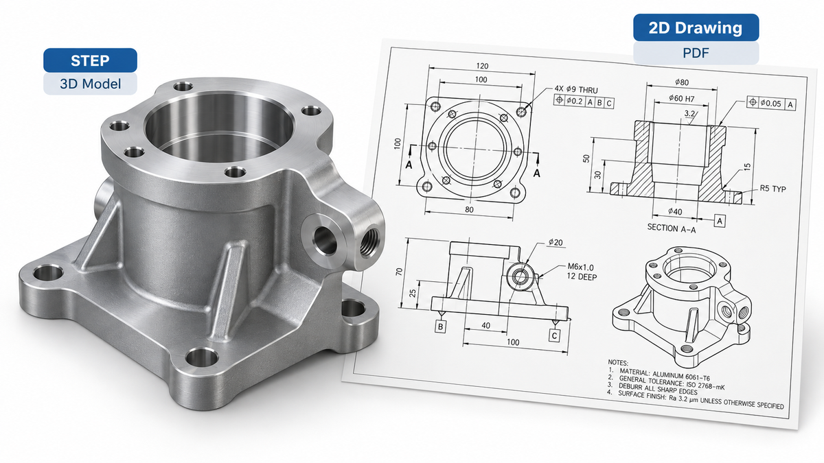
Two manufacturers can receive the same 3D model and return very different CNC machining prices. The reason is not always machine capability or labor cost. Often, the CAD model shows the shape of a part but leaves critical manufacturing requirements undefined.
For most precision CNC machining RFQs, start with a STEP (.step or .stp) solid model and a revision-controlled 2D PDF engineering drawing. Add the material grade, required quantities, surface treatment, delivery expectations, and inspection requirements. The model helps the manufacturer evaluate geometry and machining access; the drawing establishes the requirements that the finished part must meet.
Different CNC file types serve different purposes. A file suitable for CNC toolpath programming may not communicate tolerances, and a technical drawing may not provide enough geometry for efficient CAM programming. Here is how to prepare a file package that supports a more reliable quotation.

CNC File Types Compared: CAD Models, Drawings, and Machine Programs
| File type | What it communicates | Use in a machining RFQ |
|---|---|---|
| STEP (.step, .stp) | Precise 3D solid or surface geometry | Preferred neutral 3D format for most machined parts |
| Parasolid (.x_t, .x_b) | 3D solid and surface geometry | Strong alternative when supported by the supplier's CAD/CAM software |
| IGES (.igs, .iges) | Geometric entities, commonly surfaces | Useful legacy format; imported surfaces may need repair |
| Native CAD (.sldprt, .ipt, .prt, etc.) | Application-specific part features and geometry | Useful as a supplement; confirm software and version compatibility |
| STL (.stl) | Triangulated mesh approximating geometry | Reference only for many precision parts; not the preferred machining master |
| DXF / DWG (.dxf, .dwg) | 2D profiles, dimensions, and drawing entities | Useful for plate profiles, simple 2D features, and drawing exchange |
| PDF (.pdf) | Human-readable dimensions, GD&T, notes, and specifications | Essential companion for communicating product acceptance criteria |
| NC / TAP / G-code (.nc, .tap, .gcode) | Machine-specific toolpath instructions | Usually not required from the customer for a supplier quotation |
STEP is usually the safest starting point because it is widely supported and can transfer accurate CAD geometry without depending on the original design software. That does not mean every STEP export is correct: the supplier still needs to verify units, body integrity, orientation, and imported features.
IGES may be appropriate for legacy surface models. STL is different: it replaces mathematically defined surfaces with facets, which can introduce approximation errors and make precise feature recognition more difficult. An STL file can be reviewed, but a native solid model or STEP export is normally better for dimensional CNC machining.
The Three Parts of a Complete CNC Machining RFQ Package
1. A 3D model for geometry and manufacturing evaluation
Supply a separate STEP model for each part number and revision. A machinist or process engineer uses the model to evaluate the part envelope, pocket depth, tool access, internal radii, workholding options, possible setups, and the need for turning, milling, or secondary operations.
Check that the exported model contains the intended solid bodies, not just disconnected surfaces. If an assembly is required for context, include it separately from the individual component models and provide a bill of materials (BOM).

2. A 2D drawing for tolerances and acceptance criteria
A STEP model generally identifies nominal geometry, but it may not reliably transfer every tolerance, surface texture symbol, material note, or inspection instruction to a supplier's workflow. Some model-based definition systems can carry product manufacturing information (PMI); unless that workflow has been explicitly agreed, do not assume the recipient will see or interpret it correctly.
Provide a controlled PDF drawing identifying the part number and revision. The 2D drawing should state the applicable general tolerance standard, individual critical tolerances, geometric tolerances and datums, thread specifications, surface roughness, material requirements, finish, and any special manufacturing or inspection notes.
Consider two parts with nominally identical Ø10 mm holes. One is a clearance hole with a relatively broad size tolerance; the other is a precision locating bore with a specified fit and positional requirement. They look similar in a basic 3D model, but may require different tooling, finishing operations, and measurement methods. That difference belongs in the drawing and the quotation.
3. RFQ details that affect price and lead time
The drawing alone may not establish the commercial or quality scope. Include a short RFQ note or spreadsheet listing the quantities to quote, anticipated annual usage if known, prototype versus production stage, required delivery date, and whether special inspection documentation is needed.
For example, request price breaks for 10, 100, and 1,000 pieces rather than asking only for a vague “production price.” Quantity affects setup-cost allocation, fixturing, cutting strategy, inspection sampling, and purchasing of raw material. If an FAI, full dimensional report, or material certificate is required, specify it before the price is finalized.
Drawing Information That Can Change the CNC Quote
| Requirement | What the engineer or buyer should define | Why it changes the quote |
|---|---|---|
| Material | Exact alloy and condition, e.g., aluminum 6061-T6 or stainless steel 316L | Material cost, machinability, and available stock vary |
| Dimensional tolerances | General tolerance standard plus individually controlled features | Tight features may add finishing passes, tools, and inspection time |
| GD&T and datums | Position, flatness, perpendicularity, profile, or runout where functional | May change setup strategy, fixturing, and CMM programming |
| Threads and fits | Thread designation, class, depth, inserts, and mating requirements | Determines tools, operations, and gauging |
| Surface roughness | Ra or other specified parameters on the actual functional surfaces | Different areas may need fine machining, grinding, or polishing |
| Finishing | Anodizing, passivation, plating, coating, masking, and appearance requirements | Adds processing cost and may affect finished dimensions |
| Inspection | Critical-to-quality (CTQ) features, sampling plan, reports, traceability | Adds verification work and documentation scope |
 Do not apply an unnecessarily tight tolerance to every dimension. A bearing seat, sealing face, or locating hole may need additional control, while nonfunctional outer profiles often do not. Separate the critical features from general dimensions so suppliers can propose an appropriate process rather than pricing every surface as a precision feature.
Surface treatment needs particular attention. If an anodized aluminum bore must meet a tight finished size, the RFQ should identify whether the requirement applies after coating, whether masking is permitted, and what coating specification is required. A generic “black anodized” note may not be enough. Our guide to CNC machining surface finish requirements explains how roughness and post-processing interact with part function.
Five Checks Before You Export and Send CNC Files
1. Confirm units and scale. Verify whether the file is in millimeters or inches and compare a known overall dimension after exporting. Do not rely only on the recipient's default CAD settings.
2. Inspect the exported solid. Reopen the STEP file and check for missing bodies, open surfaces, incorrect hole depths, suppressed features, or geometry changes caused by translation.
3. Synchronize model and drawing revisions. A Rev B PDF paired with a Rev A model can produce an apparently valid quotation for the wrong geometry. Put the same part number and revision in every filename and the RFQ cover note.

4. Identify controlled surfaces and special processes. Highlight datum faces, CTQ bores, cosmetic areas, sharp-edge restrictions, heat treatment, coating, and any dimensions that must be checked after finishing.
5. Clarify the inspection deliverables. A standard dimensional check is not the same scope as a full CMM report, first article inspection, material traceability, or 100% verification of defined features. State what acceptance evidence is required.
Example: A CNC Machining File Package Ready for Quotation
For a hypothetical precision aluminum housing, the submitted package could be organized as follows:
-
RFQ_4821_RevC/
-
4821_RevC.step
-
4821_RevC_drawing.pdf
-
RFQ_4821_RevC_requirements.txt
-
Assembly_reference.pdf (if needed)
-
The RFQ note would state:
| RFQ field | Example specification |
|---|---|
| Part / revision | Housing 4821 / Rev C |
| Material | Aluminum 6061-T6 |
| Quantities | 10 prototype units; 100 and 1,000 for price comparison |
| Surface treatment | Black anodizing; drawing identifies masked and critical fit areas |
| Critical features | Locating bores and datum-related mounting surfaces per drawing |
| Inspection | First article dimensional report for drawing-designated features |
| Manufacturing stage | Prototype validation, with possible repeat production |
| Delivery | Requested ship date and destination to be confirmed |
This is an illustrative package, not a universal specification. The actual drawing must define the sizes, tolerances, finish standards, and inspection acceptance criteria. When conflicts are found between the model and drawing, the supplier should request written clarification before quoting or manufacturing rather than silently choosing one.
How Incomplete Files Lead to Inaccurate CNC Machining Prices
A supplier may be able to issue a budgetary estimate from a 3D model alone, especially for a simple prototype. However, the estimate may exclude operations that are not visible in nominal geometry: precision boring, grinding, masked anodizing, deburring restrictions, special thread gauges, or detailed dimensional reporting.
Once the missing requirements arrive, the supplier may need to revise the process plan, material allowance, inspection time, and price. That is not necessarily an arbitrary price increase; the scope of work has changed.

A more useful RFQ separates confirmed requirements from open questions. If a bore fit is not final, mark it “TBD—please evaluate alternatives” rather than leaving the supplier to guess. If the surface finish is flexible, invite a DFM proposal. This helps compare quotations based on a consistent technical scope and gives engineers room to suggest cost-saving changes.
If only a PDF drawing, STL mesh, or incomplete CAD model is available, send it with a clear description of what is missing. Some simple parts can still be evaluated, while complex 3D machining may require a proper solid model or additional clarification before a firm quotation is possible.
Send a More Complete RFQ to XY-GLOBAL
Before requesting a quote, prepare the latest 3D model, the matching 2D drawing, material, quantities, finishing requirements, and any critical inspection needs. If a specification is still under development, identify it explicitly so the engineering team can review manufacturability and quotation assumptions.
XY-GLOBAL supports custom CNC milling, turning, multi-axis machining, finishing, and dimensional inspection. Explore our precision CNC machining services and use the quotation form to share your project files for technical review.
FAQ
Should I send my CNC machine's G-code to a machining supplier?
Usually not. The supplier normally develops its own CAM program for its machines, tools, workholding, and process plan. Send the design definition and manufacturing requirements instead unless an agreed production transfer specifically requires programs.
Can multiple part numbers be included in one STEP file?
An assembly model can help explain interfaces, but supply separate part models with matching part numbers and revisions when you need individual quotes. Add an assembly drawing or BOM when multiple components must be supplied together.
Does a STEP file include GD&T automatically?
Not necessarily. Certain STEP and model-based definition workflows can carry PMI, but import support and interpretation vary. Unless you have agreed on a validated digital definition workflow, provide a controlled 2D drawing with the relevant GD&T.
Can confidential CNC drawings be reviewed under an NDA?
Yes. If your organization requires confidentiality protection, arrange the NDA and document-transfer procedure with the supplier before sending sensitive design data.
What if a critical dimension is still undecided?
Flag the feature as an open requirement and explain its intended function, mating part, or target fit. Request a DFM review and, if appropriate, separate price options. Do not release production against an unresolved acceptance criterion.


공유하다:
ISO 13485 Plastic Injection Molding: A Practical Guide for Medical Parts Manufacturing