


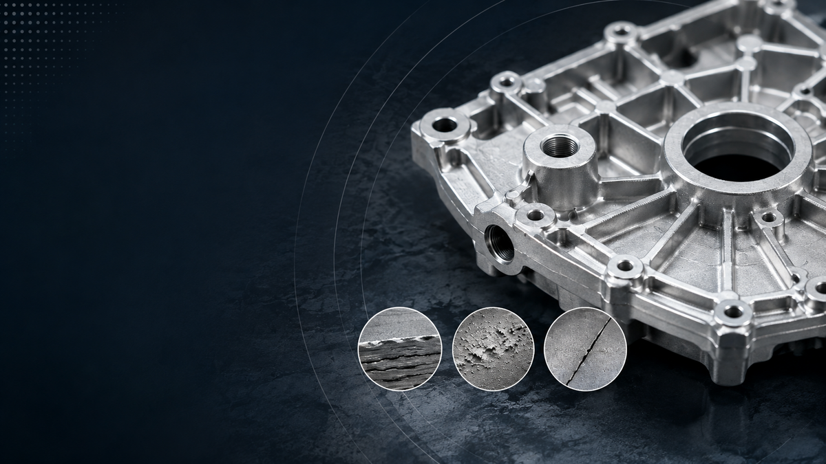
다이캐스팅(Die casting)은 용융 금속을 금형 캐비티에 고속·고압으로 주입한 뒤, 압력을 가한 상태에서 빠르게 응고시키는 제조 공정입니다.
엔지니어링 도면, 구매 문서 및 공급업체 자료에서 Al die cast는 알루미늄 다이캐스팅(aluminum die casting) 또는 알루미늄 다이캐스트 부품(aluminum die-cast parts)의 약어로 흔히 사용됩니다. 이는 일반적으로 알루미늄 다이캐스팅 공정이나 알루미늄 다이캐스트 부품을 의미합니다.
알루미늄 다이캐스팅은 우수한 치수 일관성을 갖춘 복잡한 부품을 중대량으로 생산하는 데 널리 사용됩니다. 자동차, 통신, 산업 자동화, 소비자 가전, 의료 기기 및 열 관리 분야에서 흔히 볼 수 있습니다.
다이캐스트 부품은 대개 우수한 표면 품질과 치수 안정성을 제공하지만, 부품 설계, 금형 설계, 용융 금속 상태 또는 주조 매개변수가 적절하게 제어되지 않으면 결함이 발생할 수 있습니다.
다음은 12가지 일반적인 알루미늄 다이캐스팅 결함과 그 주요 원인입니다.

1. 흐름 자국(Flow Marks)
외관
흐름 자국은 주조 표면에 줄무늬나 선 형태로 나타나며, 종종 용융 금속의 흐름 방향을 따릅니다. 경우에 따라 주변 금속과 색상이나 질감이 약간 다른 불규칙한 패턴이 표면에 보일 수 있습니다.
이러한 결함은 시간이 지나면서 커지지는 않지만 외관, 도장 품질 및 표면 균일성에 영향을 줄 수 있습니다.
주요 원인
- 금형 온도 또는 용융 알루미늄 온도가 너무 낮음
- 충전 속도가 너무 느려 금속이 너무 빨리 냉각됨
- 게이트 위치나 흐름 방향이 이상적이지 않음
- 통기(Venting) 불량
- 이형제 과다 사용 또는 분사 후 건조 부족

2. 열균열 자국(Heat Checking Marks)
외관
주조 표면에 실금 모양, 그물 모양 또는 거미줄 모양의 패턴이 나타나며, 때로는 미세하게 솟아오르거나 움푹 들어간 자국으로 보입니다. 금형을 반복적으로 사용할수록 이러한 자국은 더욱 뚜렷해지고 확산될 수 있습니다.
이러한 자국은 보통 금형 캐비티 표면의 열 피로 균열에서 비롯되어 주물로 전사된 것입니다.
주요 원인
- 금형의 반복적인 가열 및 냉각으로 인한 열 피로 발생
- 금형 예열 불균일
- 과도한 국부 냉각 또는 큰 온도 차이
- 부적절한 금형 재질, 열처리 또는 표면 유지관리

3. 콜드 셧(Cold Shut, 미융합)
외관
콜드 셧은 주조 표면에 좁고 불규칙하며 약간 움푹 들어간 선으로 나타납니다. 어떤 경우에는 표면에만 머물지만, 다른 경우에는 부품 내부로 더 깊게 연장되기도 합니다.
콜드 셧 위치에서는 두 줄기의 용융 금속이 만났으나 완전히 융합되지 못했으며, 이로 인해 강도가 저하되거나 때때로 균열로 이어질 수 있습니다.
주요 원인
- 두 금속 줄기가 온도가 너무 많이 떨어진 상태에서 만남
- 용융 금속 온도나 금형 온도가 너무 낮음
- 충전 속도가 너무 느리고 충전 시간이 너무 김
- 흐름 경로가 너무 길거나 벽 두께가 너무 얇음
- 러너(Runner) 및 게이트 설계가 적절하지 않음

4. 싱크 마크(Sink Marks, 수축 자국)
외관
싱크 마크는 보스(Boss), 리브 뿌리 또는 벽 두께 변화가 심한 영역과 같은 주물의 두꺼운 부분에 매끄러운 함몰 형태로 나타납니다.
이는 표면 수축 결함으로, 내부 수축 기공과는 다릅니다.
주요 원인
- 벽 두께의 큰 차이
- 두꺼운 섹션의 국부적 열점(Hot spots)
- 충분하지 않은 증압(Intensification pressure) 또는 보압 시간
- 국부 금형 온도가 너무 높음
- 냉각 레이아웃의 불균형
- 금형이 너무 일찍 열림

5. 이젝터 핀 자국 및 파팅 라인 자국
외관
주조 표면에 원형 이젝터 핀 자국, 국부적으로 솟아오르거나 들어간 영역, 단차 자국, 또는 파팅 라인에서의 눈에 띄는 불일치(Mismatch)가 나타날 수 있습니다.
이러한 결함은 이젝터 위치나 고정 금형과 이동 금형의 접합부, 슬라이드 또는 인서트 부위에서 발생할 수 있습니다.
주요 원인
- 마모된 이젝터 핀 끝부분 또는 이젝터 핀 높이 불일치
- 이젝터 핀 배치 불량 또는 이젝터 지지 면적 부족
- 주물과 금형 사이의 과도한 고착력
- 이동 금형과 고정 금형 사이의 체결 불량
- 슬라이드, 인서트 또는 기타 이동 부품의 유격
- 금형 정렬 정확도 부족

6. 금형 고착 및 접착 자국
외관
주조 표면에 작은 금속 조각이나 비금속 물질이 붙어 있는 모습으로 나타납니다. 이러한 부착물이 떨어진 후에는 표면이 빛나거나, 짙은 회색을 띠거나, 거칠거나, 국부적으로 뜯겨 나간 것처럼 보일 수 있습니다.
알루미늄이 금형 캐비티 표면에 달라붙는 현상을 흔히 금형 고착(Die soldering)이라고 합니다.
주요 원인
- 금형 캐비티 표면에 알루미늄 잔여물 유지
- 국부 금형 온도가 너무 높음
- 용융 금속이 동일한 영역을 고속으로 반복 타격
- 이형제 도포 부족
- 금형 표면이 거칠거나 표면층 손상
- 용융 알루미늄에 산화물이나 기타 오염물질 포함

7. 적층 및 박리(Lamination and Flakes)
외관
주물에 눈에 보이는 층상 금속 구조, 얇은 막 형태의 구조, 또는 박리될 수 있는 국부 영역이 나타납니다. 일부 적층 결함은 원재료 상태에서는 명확하지 않다가 가공이나 파괴 검사 후에야 드러나기도 합니다.
주요 원인
- 캐비티로 먼저 들어온 금속이 이미 부분적으로 응고됨
- 나중에 들어온 금속이 부분 응고된 층 위로 흐름
- 금속 충전이 불안정하거나 역류를 포함함
- 샷 플런저(Shot plunger)의 움직임이 불안정함
- 러너 시스템 설계가 부적절함
- 용융 금속 내 산화 피막이 너무 많음

8. 끌림 자국(Drag Marks)
외관
끌림 자국은 이젝션(추출) 방향으로 거친 줄무늬, 긁힘, 마모 또는 찢긴 표면 영역으로 나타납니다.
심한 경우 알루미늄이 금형 표면에 달라붙어 이후 주조되는 부품에도 동일한 결함이 반복해서 나타날 수 있습니다.
주요 원인
- 구배 각도(Draft angle) 부족
- 금형 표면이 거칠거나 알루미늄이 쌓여 있음
- 국부적 고착력이 너무 강함
- 이젝션이 불균일함
- 슬라이드 움직임이 원활하지 않음
- 이형제 부족

9. 침식(Erosion)
외관
주조 표면의 국부적인 부위에 구멍(Pit), 거친 질감 또는 솟아오른 불규칙한 패턴이 나타납니다. 이러한 결함은 보통 용융 금속이 고속으로 금형 표면을 때리는 영역에 해당합니다.생산이 계속됨에 따라 금형 침식이 심해지며 결함이 더욱 두드러지는 경향이 있습니다.
주요 원인
- 게이트 위치나 방향이 적절하지 않음
- 용융 금속이 코어나 금형 캐비티 표면을 직접 타격함
- 게이트 속도가 너무 높음
- 국부 금형 냉각 부족
- 용융 금속 온도가 장시간 너무 높게 유지됨

10. 균열(Cracks)
외관
균열은 주조 표면에 가늘고 좁으며 곧거나 구불구불한 선으로 나타납니다. 일부 균열은 취급, 가공 또는 조립 과정에서 계속 커질 수 있습니다.
다이캐스트 부품의 균열에는 열균열(Hot cracks), 냉간균열(Cold cracks), 이젝션 균열, 또는 가공 후 드러나는 내부 균열 등이 포함될 수 있습니다.
주요 원인
- 합금 조성 또는 용융 금속 품질이 불안정함
- 벽 두께 변화가 너무 급격함
- 예리한 모서리, 보스 또는 구멍이 응력 집중을 유발함
- 금형 내 체류 시간이 너무 짧음
- 주물이 금형 내에서 너무 꽉 끼어 있음
- 이젝션 위치 설계 미흡 또는 이젝션 힘 불균일
- 금형 부위 간 온도 차이가 너무 큼

11. 가스 기공 및 블리스터(Gas Porosity and Blisters)
외관
가스 기공은 주물 내부나 가공면에 둥글거나 타원형, 또는 불규칙한 구멍 형태로 나타납니다.
일부 기공은 원재료 상태에서는 보이지 않다가 CNC 가공, 연마, 샌드블라스팅 또는 열처리 후에만 나타나기도 합니다. 경우에 따라 포획된 가스가 고온에서 팽창하여 표면에 기포(블리스터)를 유발합니다.
주요 원인
- 금형 충전 중 공기 포획
- 통기 또는 진공 성능 부족
- 저속 샷 속도가 너무 높음
- 금속 흐름이 난류(Turbulent)를 형성함
- 이형제나 수분이 완전히 증발하지 않음
- 탈가스(Degassing) 부족
- 용융 알루미늄 내 수소 함량이 너무 높음
- 러너 설계가 제팅(Jetting)과 난류를 유발함

12. 플래시 및 버(Flash and Burrs)
외관
파팅 라인, 슬라이드 부위, 인서트 접합부, 이젝터 부위 또는 통기구 위치에 얇은 금속 찌꺼기가 나타납니다.
매우 얇은 플래시는 종종 날카로운 버(Burr)가 되어 외관, 조립 및 후가공 비용에 영향을 줍니다.
주요 원인
- 형체력(Clamping force) 부족
- 사출 압력이 너무 높음
- 파팅 면에 알루미늄 찌꺼기나 이물질이 있음
- 파팅 면, 슬라이드 또는 인서트 마모
- 금형 맞춤 간격이 너무 큼
- 금형 강성 부족 또는 국부적 금형 변형

알루미늄 다이캐스팅 결함의 일반적인 검사 방법
결함마다 필요한 검사 방법이 다르지만, 모든 부품에 고급 테스트가 필요한 것은 아닙니다.
육안 검사
흐름 자국, 싱크 마크, 플래시, 끌림 자국, 이젝터 자국 및 눈에 보이는 균열을 확인하는 가장 일반적인 방법입니다.
침투 탐상 검사(Dye Penetrant Inspection)
주로 알루미늄 다이캐스트 부품의 개방형 표면 균열 및 표면 연결형 콜드 셧을 감지하는 데 사용됩니다.
X-레이 또는 산업용 CT
가스 기공, 수축 기공, 개재물, 적층과 같은 내부 결함에 적합합니다. 산업용 CT는 더 완벽한 3D 내부 정보를 제공하지만 비용이 더 높습니다.
누설 테스트(Leak Testing)
액체 냉각 하우징, 밸브 본체, 펌프 본체 등 밀폐된 캐비티에 흔히 사용되며, 기공, 콜드 셧 또는 균열과 같은 관통 결함이 누설을 유발하는지 확인합니다.
단면 절단 및 금속 조직 분석
주로 결함 분석, 특히 기공, 수축, 박리, 균열 및 내부 구조 평가에 사용됩니다.
부품별 주요 결함 판단 기준
일반 외장 부품의 경우 주요 관심사는 흐름 자국, 끌림 자국, 플래시, 이젝터/파팅 자국 및 열균열 자국입니다.
CNC 가공이 필요한 부품의 경우 내부 기공, 수축, 적층 및 가공 후 노출되는 표면 결함이 주요 관심사입니다.
구조용 부품의 경우 균열, 콜드 셧, 내부 수축 및 기계적 무결성이 핵심입니다.
액체 냉각 하우징, 밸브 본체 및 기타 밀폐 부품의 경우 가스 기공, 콜드 셧, 균열이 특히 중요하며, 종종 누설 테스트가 요구됩니다.
따라서 Al 다이캐스트 부품의 결함 수용 기준은 표면 외관뿐만 아니라 제품의 실제 기능, 조립 위치 및 품질 요구 사항에 기반해야 합니다.
FAQ
Al die cast는 무엇을 의미하나요?
“Al”은 알루미늄의 화학 기호이자 일반적인 약어입니다. “Al die cast”는 일반적으로 알루미늄 다이캐스팅 또는 알루미늄 다이캐스트 부품을 의미합니다. 공식 기술 문서에서는 aluminum die casting, aluminum die-cast parts, die cast aluminum parts와 같은 표현이 더 흔히 사용됩니다.
알루미늄 다이캐스트 부품에 기공이 생기기 쉬운 이유는 무엇인가요?
고압 다이캐스팅에서는 충전 속도가 매우 빠릅니다. 금속 흐름이 불안정하거나 통기 성능이 떨어지거나 용융 알루미늄에 가스가 너무 많으면, 공기가 주물 내부에 갇혀 기공을 형성할 수 있습니다.
콜드 셧과 균열의 차이는 무엇인가요?
콜드 셧은 두 줄기의 용융 금속이 만났으나 완전히 융합되지 못했을 때 형성됩니다. 균열은 응고, 수축, 이젝션 또는 이후 하중 과정에서 발생하는 재료 분리 현상입니다.
벽 두께가 다이캐스팅 품질에 영향을 미치나요?
네. 벽이 너무 얇으면 불완전 충전 및 콜드 셧이 발생할 수 있고, 두꺼우면 싱크 마크 및 내부 수축이 발생할 수 있습니다. 갑작스러운 벽 두께 변화는 응력 집중과 균열을 유발할 수 있습니다.
결론
일반적인 Al 다이캐스트 결함으로는 흐름 자국, 콜드 셧, 싱크 마크, 금형 고착, 균열, 기공 및 플래시가 있습니다.
이러한 결함은 부품 설계, 금형 설계, 용융 금속 품질, 사출 매개변수, 통기 상태 및 금형 온도와 관련이 있습니다. 많은 경우 하나의 결함이 여러 요인이 복합적으로 작용하여 발생하므로, 결함 명칭만으로 원인을 단정할 수 없습니다.
실제 생산에서는 결함의 위치, 금속 흐름 방향, 금형 구조 및 공정 매개변수를 결함과 함께 분석하여 문제의 근본 원인을 파악하고 안정적인 주조 품질을 유지하는 것이 중요합니다.


공유하다:
CMM 검사란 무엇인가: 정밀 CNC 부품 검증 방법
맞춤형 황동 CNC 가공 서비스 | 정밀 황동 부품