


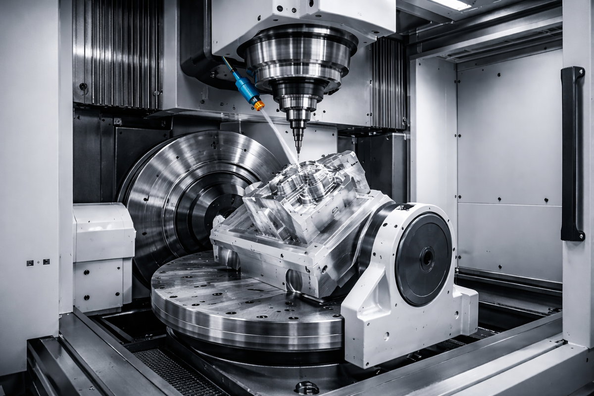
CNC machining is widely used for producing precision components in industries such as medical devices, robotics, automotive, aerospace, semiconductor equipment, and industrial automation.
However, even with advanced CNC machines, manufacturers may still encounter problems such as:
- unstable dimensions
- excessive tool wear
- machining vibration
- poor chip control
- thread defects
- inconsistent surface finish
These issues can reduce production efficiency, increase scrap rates, and affect final product performance.
Understanding the causes behind common CNC machining problems helps engineers optimize cutting parameters, improve process stability, and achieve consistent part quality.
This article explains 23 practical CNC machining problems and solutions based on real production experience.
1. How Do Cutting Parameters Affect CNC Machining Quality?
Cutting parameters directly influence cutting force, heat generation, tool life, and surface quality.
The three main machining parameters are:
- cutting speed
- feed rate
- depth of cut
Among these parameters:
- Cutting speed has the greatest influence on tool life and cutting temperature.
- Feed rate strongly affects cutting force and surface finish.
- Depth of cut directly increases cutting load.
For example, increasing the depth of cut increases the amount of material removed per pass, which significantly increases cutting force.
A proper balance between speed, feed, and depth of cut is essential for stable CNC machining.

2. How Do Cutting Parameters Influence Cutting Force?
Cutting force changes differently depending on each machining parameter.
General machining experience:
- When depth of cut doubles, cutting force usually increases significantly.
- When feed rate increases, cutting force rises because more material is removed per revolution.
- Increasing cutting speed may slightly reduce cutting force in some machining conditions, but excessive speed accelerates tool wear.
Therefore, higher cutting speed does not always mean better productivity.
The optimum machining condition depends on:
- material hardness
- tool material
- machine rigidity
- cooling condition
- required surface finish
3. How Can You Determine Whether Cutting Force Is Too High?
In production environments, cutting force is not always measured directly. Engineers usually evaluate machining conditions through practical indicators.
Common signs of excessive cutting force include:
Poor chip evacuation
Long, tangled chips may interfere with cutting and damage the workpiece surface.
Excessive cutting temperature
High heat accelerates tool wear and may cause dimensional instability.
Abnormal chip shape or color
Chip color can provide a rough indication of cutting temperature.
Typical reference:
| Chip Color | Approximate Temperature |
|---|---|
| White | Below 200°C |
| Yellow | 220–240°C |
| Blue | 320–350°C |
| Purple/black | Above 500°C |
Actual temperature varies depending on material, tool coating, coolant, and cutting conditions.
4. Why Does CNC Tool Rubbing Occur During Arc Machining?
During CNC turning, a tool may rub instead of cutting when the tool geometry does not match the programmed contour.
Common causes include:
- incorrect starting point calculation
- incorrect tool nose radius compensation
- unsuitable approach angle
- insufficient clearance during concave arc machining
For example, when the actual workpiece diameter differs significantly from the programmed value, the secondary cutting edge may contact the material instead of removing chips.
Solutions:
- verify tool geometry
- check tool nose radius compensation
- confirm workpiece dimensions before machining

5. How to Reduce CNC Tool Wear and Extend Tool Life?
Tool wear is one of the most common CNC machining problems.
Major causes include:
Excessive cutting speed
Higher speed increases heat generation and accelerates insert wear.
Incorrect feed rate
Too high feed increases cutting force, while too low feed may cause rubbing instead of cutting.
Poor cooling
Insufficient coolant reduces heat removal and shortens tool life.
Low machine rigidity
Machine vibration causes uneven cutting loads and premature tool failure.
To improve tool life:
- optimize cutting parameters
- select suitable inserts
- control tool replacement cycles
- improve fixture rigidity
6. Why Do CNC Parts Become Out of Tolerance?
Dimensional instability is one of the biggest concerns in precision machining.
Common reasons include:
| Cause | Solution |
|---|---|
| Tool wear | Monitor tool life and replace tools before excessive wear |
| Workpiece movement | Improve clamping method |
| Thermal expansion | Control coolant and machining temperature |
| Machine vibration | Improve rigidity |
| Incorrect compensation | Verify CNC offsets |
A new cutting tool usually produces stable dimensions because cutting force is lower.
As the tool wears:
- cutting resistance increases
- vibration may increase
- the workpiece may shift slightly in the fixture
This can result in dimensional deviation.
7. Why Do CNC Machined Threads Fail?
Thread machining defects are common in precision components.
Typical problems include:
- incorrect thread depth
- damaged thread profile
- oversized or undersized threads
- poor pitch accuracy
- tool vibration during threading
For thread cutting:
- External thread depth is usually around 1.3 × pitch.
- Internal thread depth is usually around 1.08 × pitch.
Proper spindle speed, tool geometry, and cutting sequence are important for producing accurate threads.
A common reference formula:
Spindle Speed = 1200 ÷ Pitch × Safety Factor
The actual value should be adjusted according to:
- material
- thread diameter
- machine capability
- tool manufacturer recommendation
8. How Does Tool Nose Radius Affect CNC Turning Quality?
Tool nose radius directly affects:
- surface finish
- cutting force
- vibration tendency
- tool strength
A larger nose radius can improve surface finish because it creates a smoother cutting path.
However, an excessively large nose radius increases cutting force and may cause vibration, especially when machining:
- thin-wall parts
- deep cavities
- low-rigidity components
Typical practice:
- rough machining: larger nose radius for strength
- finishing: select radius based on tolerance and surface requirement
Choosing the correct tool geometry is essential for balancing productivity and quality.
9. How Should CNC Machining Parameters Be Adjusted When Feed Rate Changes?
Feed rate has a direct impact on:
- cutting force
- chip thickness
- surface finish
- tool wear
When increasing feed rate, spindle speed and cutting conditions should be reviewed together.
A common production adjustment method is:
- Increase feed rate carefully to improve productivity.
- Reduce spindle speed slightly if cutting force or temperature becomes excessive.
- Monitor chip shape and surface finish after adjustment.
The correct adjustment depends on:
- material type
- insert geometry
- tool coating
- machine rigidity
Simply increasing feed rate without optimizing other parameters may cause:
- tool chipping
- poor surface finish
- dimensional variation
10. Why Does Increasing Cutting Speed Sometimes Damage CNC Tools?
Many engineers assume higher cutting speed always improves efficiency. However, excessive cutting speed can significantly reduce tool life.
At an appropriate range:
- higher cutting speed can improve productivity
- cutting force may decrease slightly
- chips can carry away more heat
However, when speed exceeds the tool’s capability:
- cutting temperature rises rapidly
- coating wear accelerates
- cutting edge strength decreases
- tool failure may occur
The correct cutting speed depends on:
- workpiece material
- carbide grade
- coating technology
- coolant method
- machining operation
For difficult materials such as stainless steel, titanium alloys, and hardened steels, tool life management becomes especially important.
11. Why Does CNC Machining Experience Vibration Problems?
Machining vibration, also called chatter, is one of the most common causes of poor surface quality.
Typical symptoms:
- visible vibration marks
- unstable dimensions
- abnormal cutting noise
- shortened tool life
Common causes include:
Excessive tool overhang
A long tool extension reduces rigidity and increases vibration.
Weak workholding
Poor clamping allows the workpiece to move during cutting.
Incorrect cutting parameters
Too aggressive cutting conditions can exceed machine stability.
Insufficient machine rigidity
Small machines may struggle with heavy cutting operations.
Solutions:
- reduce tool overhang
- improve fixture design
- optimize cutting parameters
- select stronger tool holders
For precision CNC machining, rigidity is often more important than simply increasing cutting speed.
12. How Can Manufacturers Improve CNC Machining Efficiency?
Improving CNC efficiency is not only about faster cutting.
A stable process requires optimization of:
- tooling
- programming
- inspection methods
- production planning
Practical methods include:
Optimize tool usage
A properly managed tool life system prevents unexpected tool failure.
Reduce unnecessary tool changes
For stable processes, one tool completing a full operation is usually better than frequent replacement.
Improve programming efficiency
Optimized tool paths reduce:
- air cutting time
- tool movement
- machining cycle time
Use suitable machining strategies
High-speed machining typically uses:
- higher cutting speed
- higher feed rate
- smaller depth of cut
This allows more heat to leave with chips and reduces heat transfer into the workpiece.
13. Why Do Grooving Tools Vibrate or Break?
Grooving operations are more sensitive than normal turning because cutting forces are concentrated in a narrow cutting edge.
Common causes:
Excessive cutting force
Caused by:
- excessive depth of cut
- improper feed rate
- unsuitable insert geometry
Poor tool rigidity
Caused by:
- long tool extension
- weak tool holder
- incorrect installation
Poor chip evacuation
Long chips may become trapped in the groove and damage the insert.
Solutions:
- shorten tool overhang
- select proper groove width
- optimize feed and cutting speed
- improve coolant direction
14. Why Do CNC Parts Move During Machining?
Part movement during machining is a major reason for dimensional inconsistency.
Common causes:
- insufficient clamping force
- improper fixture design
- excessive cutting force
- worn chuck jaws
- unstable workholding position
When cutting begins:
- a new tool generates lower resistance
- dimensions may initially remain stable
As the tool wears:
- cutting force increases
- the workpiece may shift slightly
- dimensions begin to drift
For precision components, fixture design is as important as cutting parameters.
15. How Do CNC Manufacturers Control Programming Errors?
Incorrect CNC programming can directly affect machining quality.
Common programming-related issues include:
- incorrect machining coordinates
- wrong tool compensation
- improper cycle parameters
- incorrect reference points
For example, CNC turning roughing cycles such as G71 require correct parameter settings and program sequence references.
To reduce programming errors:
- verify programs before production
- conduct first article inspection
- simulate tool paths when possible
- maintain standardized programming procedures
16. Why Is CNC Inspection Important for Machining Quality?
Precision machining is not complete without proper inspection.
A reliable CNC manufacturing process usually includes:
First Article Inspection (FAI)
The first completed part is fully checked before mass production.
Dimensional Inspection
Common equipment:
- CMM (Coordinate Measuring Machine)
- height gauge
- micrometer
- caliper
Process Monitoring
Manufacturers monitor:
- critical dimensions
- tool wear
- surface finish
- machining consistency
For high-precision industries such as medical, aerospace, and semiconductor equipment, inspection capability is a key factor when selecting a CNC machining supplier.
17. How Do Material Properties Affect CNC Machining Performance?
Different materials require different machining strategies.
Examples:
Aluminum alloys
Characteristics:
- excellent machinability
- high cutting speed capability
- good surface finish
Challenges:
- chip control
- burr formation
Stainless steel
Characteristics:
- high strength
- work hardening tendency
Challenges:
- tool wear
- heat accumulation
Copper alloys
Characteristics:
- excellent thermal conductivity
Challenges:
- sticky chips
- unstable cutting conditions
Titanium alloys
Characteristics:
- high strength-to-weight ratio
Challenges:
- low thermal conductivity
- high cutting temperature
Selecting correct tooling and parameters according to material properties is essential for stable production.
18. How Can Deep Hole Drilling Problems Be Reduced?
Deep hole drilling is challenging because chip evacuation becomes difficult as hole depth increases.
Common problems include:
- drill breakage
- excessive hole deviation
- poor surface finish
- overheating
Practical solutions include:
Improve chip evacuation
Proper flute geometry helps remove chips smoothly.
Reduce drill deflection
A shorter drill length improves rigidity.
Optimize drilling parameters
Excessive feed can overload the cutting edge.
Use suitable drill geometry
For stainless steel and difficult materials, proper edge preparation helps prevent slipping and excessive cutting force.
For deep holes, stability is usually more important than maximum cutting speed.
19. How Does Material Preparation Affect CNC Machining Quality?
The starting material condition can influence final part accuracy.
Common preparation methods include:
- machining one part from one blank
- machining multiple parts from one bar
- full bar machining
Material factors that affect machining include:
- internal stress
- material hardness variation
- grain structure
- heat treatment condition
For threaded components, unstable material structure may contribute to:
- uneven thread formation
- dimensional variation
- poor surface quality
Selecting qualified raw material and controlling incoming inspection are important steps before machining begins.
20. How Can CNC Macro Programming Improve Production Efficiency?
For repeated CNC machining operations, macro programming can improve production efficiency.
Benefits include:
- shorter programs
- easier parameter adjustment
- reduced programming repetition
- improved process consistency
Typical applications:
- repeated drilling patterns
- variable machining dimensions
- customized production cycles
However, macro programming should be combined with proper process control. A well-written program cannot compensate for incorrect tooling, poor fixturing, or unsuitable cutting conditions.
21. How Can Hole Accuracy Be Improved During CNC Machining?
Hole machining problems are common in precision components.
Typical defects include:
- excessive hole runout
- incorrect diameter
- poor surface finish
- hole position deviation
Possible causes:
- insufficient drill rigidity
- tool deflection
- incorrect cutting parameters
- unstable workholding
Solutions:
- use shorter and more rigid tools
- perform drilling with suitable parameters
- use reaming or boring operations when tighter tolerance is required
- inspect critical holes with precision measurement equipment
For high-accuracy holes, machining strategy should be selected based on:
- tolerance requirement
- hole depth
- material
- production volume
22. How Can Chip Control Be Improved in CNC Turning?
Poor chip control can interrupt production and damage machined surfaces.
Common chip problems:
- long tangled chips
- chip blockage
- scratched surfaces
- unstable cutting
Effective chip control depends on:
Proper cutting parameters
Feed rate and depth of cut strongly affect chip shape.
Correct insert geometry
Different chip breakers are designed for different materials and operations.
Proper tool positioning
Incorrect tool height or cutting angle may reduce chip-breaking performance.
For small internal turning operations, special attention is required because chip evacuation space is limited.
23. What Should Be Considered When CNC Machining Copper Components?
Copper and copper alloys have excellent thermal conductivity but can be challenging to machine.
Common issues include:
- sticky chips
- poor chip breaking
- unstable cutting
- surface marks
For internal copper machining:
- a suitable tool nose radius can improve cutting stability
- proper cutting parameters help prevent chip accumulation
- sharp cutting edges reduce material deformation
For some copper applications, increasing tool nose radius from R0.4 to R0.8 may improve surface finish, but the final selection depends on:
- part geometry
- wall thickness
- tolerance requirement
How CNC Manufacturers Control Machining Quality
Solving CNC machining problems requires more than adjusting cutting parameters.
A reliable CNC machining supplier needs a complete quality control system covering the entire production process.
1. Engineering Review and DFM Analysis
Before production, engineers review:
- part geometry
- machining difficulty
- tolerance requirements
- surface finish requirements
- fixture design
Early DFM feedback helps prevent production issues before machining begins.
2. Precision Machining Equipment
Stable machining requires suitable equipment.
Typical CNC capabilities include:
- 3-axis CNC machining
- 4-axis CNC machining
- 5-axis CNC machining
- CNC turning
- Swiss machining
- EDM machining
Different machines are selected according to:
- part complexity
- material
- tolerance requirement
- production volume
3. Process Inspection and Measurement
Quality control methods include:
- CMM inspection
- dimensional measurement
- surface roughness testing
- material verification
- first article inspection
For critical dimensions, inspection reports can be provided to verify compliance with customer drawings.
4. Tool and Process Management
Production stability depends on:
- controlled tool replacement cycles
- optimized cutting parameters
- standardized machining procedures
- experienced operators
A mature machining process reduces:
- scrap rate
- rework
- delivery risk
Why Choose XY-GLOBAL for CNC Machining Projects?
At XY-GLOBAL, we provide precision manufacturing solutions for customers in medical, robotics, automation, automotive, semiconductor, and industrial equipment industries.
Our capabilities include:
- CNC machining
- CNC turning
- 3/4/5-axis milling
- die casting
- MIM/CIM
- sheet metal fabrication
- surface finishing
- precision inspection
- assembly services
With engineering support from DFM review to mass production, we help customers reduce machining risks and improve part reliability.
Our quality management system supports projects requiring strict dimensional control and consistent production performance.
Whether you need prototype machining or production-volume manufacturing, our team can review your drawings and provide practical manufacturing recommendations.
Send us your 2D drawings or 3D CAD files for a machining feasibility review and quotation.
FAQ
1. What are the most common CNC machining problems?
The most common CNC machining problems include dimensional instability, tool wear, vibration, poor chip control, thread defects, and surface finish issues.
2. How can CNC machining accuracy be improved?
CNC machining accuracy can be improved by optimizing cutting parameters, selecting suitable tooling, improving fixture rigidity, controlling temperature, and performing precise inspection.
3. Why do CNC tools break during machining?
Tool breakage is usually caused by excessive cutting force, vibration, improper cutting parameters, insufficient rigidity, or incorrect tool selection.
4. How do CNC manufacturers ensure part quality?
Professional CNC manufacturers use DFM review, process control, tool management, CMM inspection, and first article inspection to maintain consistent quality.
5. What information is needed for a CNC machining quotation?
A CNC machining supplier usually needs:
- 2D drawings
- 3D CAD files
- material requirement
- quantity
- surface finish requirement
- tolerance specifications


Share:
Custom Aluminum Die Casting Parts Supplier For OEM Components
Understanding CNC Machining for Optics Industry