


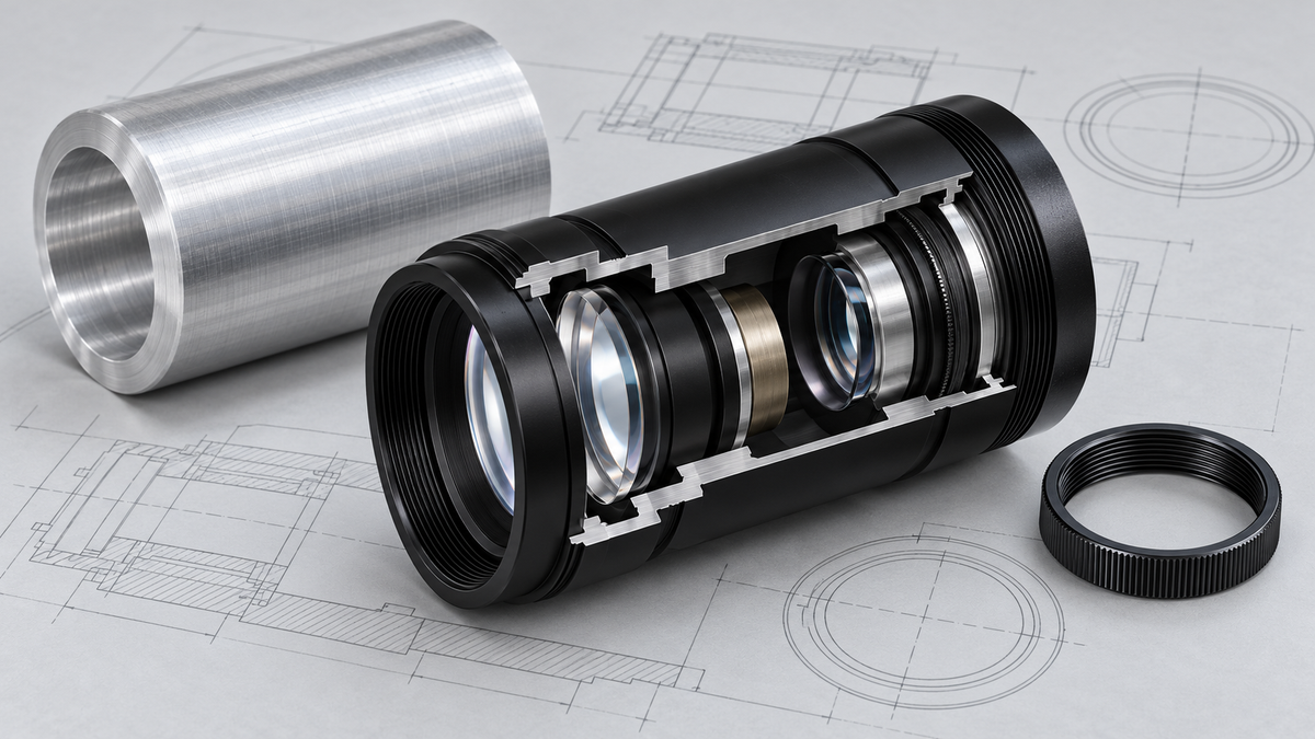
A lens can meet its optical specification and still perform poorly after installation. Excessive radial clearance can allow decentering, an uneven shoulder can introduce tilt, and a retaining ring can apply enough force to distort the optic. These problems often begin with the mechanical design surrounding the lens.
Effective lens barrel design starts with the optical alignment requirements, then defines the material, locating features, fits, retention method and inspection plan needed to preserve them. CNC manufacturing considerations belong in that process before the drawing is released.
This guide focuses on the mechanical design of custom metal lens barrels for imaging, laser, machine vision and related optical systems. It explains how to translate assembly requirements into manufacturable features, rather than how to design or manufacture the glass elements themselves.

Define Optical and Assembly Requirements
Before selecting materials or tolerances, establish how each lens will be located and retained. The barrel must preserve the required relationships between optical elements and provide a repeatable interface with the surrounding instrument.
- Radial location: A bore, separate cell or adjustable support establishes the lens position across the optical axis.
- Axial location: Shoulders and spacers establish the positions and separation of the elements.
- Retention: A retaining ring, compliant element or specified bonding arrangement holds the optic against its support.
- System interface: A pilot diameter, flange or other mounting feature locates the barrel within the final assembly.
The design inputs should include lens diameter and edge-thickness tolerances, allowable decenter and tilt, clear aperture, operating temperature range, vibration conditions and assembly access.
Also decide whether the assembly will rely on passive placement or active alignment. A clearance-fit bore alone cannot guarantee that the optical axis will coincide with the barrel axis. Lens centration errors and the available assembly movement also contribute.
Where adjustment is required, define the direction, range and resolution before finalizing the housing. An assembly that needs alignment after installation may require access holes, adjustment features or a separate lens cell.
Select Lens Barrel Materials
Material selection affects weight, thermal response, machining and finishing. Consider these factors together rather than choosing an alloy solely for strength.
| Material | Reasons to consider it | Design considerations |
|---|---|---|
| Aluminum 6061-T6 | Low weight, practical machining and established anodizing options | Evaluate differential expansion relative to the optic and the finished fit after anodizing. |
| Aluminum 7075-T6 | Higher strength when structural loading justifies it | Compare corrosion protection, finishing requirements and material condition with the application. |
| Stainless steel | Useful where corrosion resistance, wear or structural requirements favor steel | Specify the grade and account for added mass and machining requirements. |
| Titanium alloy | Useful when weight, corrosion resistance and thermal behavior support the choice | Evaluate material cost, machining difficulty and threaded-interface behavior. |
For a production design, verify material properties for the actual alloy, condition and optical material. The thermal relationship between the barrel and the lens matters more than a generic description such as “low-expansion metal.”
Changing the material late in development can change both the thermal fit and the manufacturing plan. Treat such a change as an engineering review item rather than a direct substitution.

Calculate Clearances and Tolerance Stacks
Radial clearance determines the available movement
A locating bore must accommodate lens diameter variation, bore variation, surface treatment and temperature. Excessive clearance permits movement; insufficient clearance can prevent assembly or place unintended load on the glass.
Illustrative example: Assume the finished barrel bore is 25.020–25.030 mm and the lens outside diameter is 24.990–25.000 mm.
- Minimum diametral clearance: 25.020 − 25.000 = 0.020 mm.
- Maximum diametral clearance: 25.030 − 24.990 = 0.040 mm.
- For ideal circular features, the corresponding radial clearance is 0.010–0.020 mm.
At maximum clearance, the lens center could move 20 μm from the bore center before contact. This calculation excludes bore form error and any offset between the lens edge and its optical axis.
Whether that fit is acceptable depends on the optical alignment budget and mounting method. These dimensions illustrate the calculation; they are not recommended tolerances for all lens barrels.
Axial spacing depends on the complete contact stack
Check lens edge thicknesses, spacer lengths, shoulder locations and the actual seating arrangement. Dimensions should relate to the mechanical contact surfaces used during assembly, which must then be connected to the optical prescription.
For example, controlling the overall barrel length does not necessarily control the distance between two lens seats. Those seats need dimensions and tolerances that express their functional relationship.
A worst-case stack evaluates the specified dimensional extremes. Statistical analysis can support production planning when assumptions about distributions, independence and process behavior are justified. It should not replace a required worst-case check without engineering agreement.
Specify Datums and Geometric Tolerances
A correct bore diameter does not establish its relationship to the instrument mounting interface. Define the datum reference frame around how the barrel actually locates in the assembly.
A flange-mounted design might use a mounting face and pilot diameter as functional references. Their precedence, and the controls applied to the remaining features, must follow the actual locating scheme.
| Feature | Functional question | Requirements to evaluate |
|---|---|---|
| Lens locating bore | Where can the lens sit relative to the mounting interface? | Size, form and datum-related location or orientation |
| Lens seat | Does the optic contact its intended support without excessive tilt? | Axial location, contact geometry and orientation |
| Multiple internal seats | Are the elements positioned consistently relative to one another? | Spacing, shared references and accumulated alignment error |
| Retaining thread | Does the ring engage correctly and apply the intended load? | Thread designation, fit, engagement and relationship to the seat |
Use the drawing’s specified GD&T standard and edition consistently. Position, profile, perpendicularity and runout address different requirements and are not interchangeable.
Avoid applying the tightest tolerance to every feature. Allocate manufacturing and inspection effort to the relationships that affect lens alignment, assembly and function.

Check Thermal Fit and Lens Retention
Room-temperature fit is only one operating condition. Different thermal expansion rates can change the clearance between the barrel and optic.
For a simplified, freely expanding bore-and-lens pair, the change in diametral clearance can be estimated as:
Change in clearance ≈ (barrel CTE × bore diameter − lens CTE × lens diameter) × temperature change.
If the two diameters are approximately equal, this becomes:
ΔC ≈ D × (αbarrel − αlens) × ΔT.
Using assumed values of D = 25 mm, αbarrel = 23 × 10−6/K, αlens = 7 × 10⁻⁶/K and a 40 K temperature increase gives a clearance increase of approximately 0.016 mm, or 16 μm.
This illustrative calculation assumes uniform temperature and free expansion. It excludes constraints, contact forces, thermal gradients and temperature-dependent properties. Evaluate both hot and cold conditions using verified material data.
Control how the retaining feature contacts the optic
A threaded retaining ring should contact the specified support region without obstructing the clear aperture or placing unintended load on a bevel or optical surface. Provide sufficient engagement and assembly-tool access.
Assembly torque is not a universal measure of lens preload. Thread and contact friction influence the resulting force, so a torque requirement needs an appropriate assembly procedure and validation.
Where compliance is needed, evaluate stiffness, travel and alignment behavior. A compliant axial retainer does not automatically provide radial centering. The correct arrangement depends on the complete mounting concept.
Design for CNC Machining
Rotational features often suit CNC turning. Flats, radial holes and mounting details may require milling or additional operations. Select the process around feature relationships rather than assuming every barrel requires five-axis machining.
- Preserve references: Where practical, machine related bores and seats from a shared setup to reduce datum-transfer error.
- Provide tool clearance: Deep, narrow bores and internal shoulders can restrict boring-bar reach and chip evacuation.
- Allow corner relief: Check whether a tool radius or undercut is needed for the lens or spacer to seat fully.
- Support thin walls: Evaluate wall height, diameter, unsupported length and clamping forces together.
- Plan deburring: Internal thread exits and cross-holes must remain accessible without damaging optical support surfaces.
- Preserve assembly access: Retaining-ring tools need room to engage without contacting the optic.
There is no universal minimum wall thickness for a lens barrel. A short ring and a long tube with the same wall thickness can behave differently during machining, handling and inspection.
Discuss these features during the design and engineering review, before tooling, finishing and inspection assumptions become part of the production plan.
Specify Surface and Coating Requirements
Different surfaces perform different jobs. A locating bore needs suitable fit and form; a lens seat needs controlled contact; an internal wall may need a defined stray-light treatment. One general surface-finish note cannot describe all these requirements.
For light-sensitive surfaces, define the optical performance needed at the operating wavelengths and relevant angles. Black appearance and an Ra value alone are insufficient acceptance criteria. Evaluate baffles and internal geometry against both the clear aperture and stray-light requirements.
Identify dimensions that apply after anodizing
Anodizing converts part of the aluminum surface and produces outward growth. Coating thickness and dimensional growth are therefore different quantities.
Dimensional allowance should follow the applicable finish specification and the confirmed processing capability for the component. Do not apply a single coating-growth assumption to every anodizing type, alloy and geometry.
State the anodizing type, required thickness where relevant, masking areas and final dimensional requirements. For a tight bore, compare pre-machining allowance, masking and any permitted post-treatment finishing. Each option changes the functional or protective condition of the surface.
Confirm whether final acceptance applies after all specified processing. A bore that passes inspection before treatment may not meet its finished fit requirement.

Define Inspection Requirements
Inspection should verify the characteristics that control assembly function. Instrument selection depends on feature access, geometry, surface condition and the measurement uncertainty needed for the tolerance.
A CMM can evaluate many geometric relationships, while other instruments may be more suitable for particular bore, thread, form or roughness requirements. Agree on the measurement approach for difficult features before production.
For thin walls and critical bores, define measurement locations, part support and whether acceptance applies in a free or constrained state. Where surface treatment affects fit, inspect the specified finished condition.
Dimensional acceptance of the barrel does not establish the optical performance of the assembled system. Include alignment or optical testing in the validation plan wherever the application requires it.
Lens Barrel Design Checklist
A complete drawing package reduces assumptions and makes supplier quotations easier to compare. Prepare the following information:
- Matching files: A STEP model and controlled engineering drawing with the same part number and revision.
- Material: The alloy, condition and any required material documentation.
- Optical interfaces: Lens interface dimensions, clear aperture and alignment requirements.
- Datums and tolerances: Functional references, critical dimensions and relevant geometric controls.
- Surface treatment: Finish specification, masking areas and post-treatment dimensions.
- Retention: Ring or support details, engagement, assembly access and any validated preload requirements.
- Inspection: Critical characteristics, acceptance conditions and required reports.
- Delivery scope: Cleaning, handling, packaging, quantities and requested delivery dates.
If a requirement is still under development, identify it as an open item. Explain its function and request a manufacturability review rather than allowing an unresolved tolerance or finish condition to become an unstated production assumption.
FAQ
What is the best material for a lens barrel?
There is no single best material. Aluminum is often practical for lightweight machined barrels, while other metals may better suit particular thermal, structural or environmental requirements. Compare the complete assembly and finishing requirements before selecting a grade.
What tolerances should a lens barrel use?
Start with allowable optical decenter, tilt and spacing variation, then allocate requirements to the mechanical features. Applying the same tight tolerance everywhere can increase cost without controlling the relationships that matter.
Should the lens be a press fit in the barrel?
Do not assume interference is appropriate for a glass optic. Evaluate contact stress, operating temperature, assembly method and optical sensitivity. A clearance fit, adjustable cell or compliant mounting arrangement may be more suitable.
Does a fine thread guarantee accurate focusing?
A smaller pitch provides less nominal travel per revolution for a single-start thread. Actual focus behavior also depends on backlash, thread geometry, guidance, lubrication and locking. Specify the adjustment performance the assembly requires.
Is black anodizing sufficient for stray-light control?
Suitability depends on the wavelength range, geometry and system requirements. Specify or validate the relevant optical behavior rather than accepting color alone as proof of performance.
Review Your Design Before Production
A production-ready lens barrel drawing connects optical requirements with measurable mechanical features. Before release, confirm the locating scheme, clearance across temperature, retention method, finishing allowance and inspection conditions.
For aluminum designs, our guide to black anodizing for CNC-machined parts provides additional finishing considerations. If you are comparing suppliers, the custom lens barrel manufacturer guide explains the capabilities and documentation to discuss.
XY-GLOBAL supports custom optical mechanical components through drawing review, CNC manufacturing and finishing evaluation. Share your matching model and drawing, critical lens interfaces, operating conditions and inspection requirements to request a lens barrel manufacturability review before releasing the production drawing.
Technical References
- Lens Barrel Optomechanical Design Principles — background on material selection, mounting arrangements and environmental considerations.
- Edmund Optics: Important Concepts for Selecting Optical Component Mounts — positioning constraints and adjustment considerations.
- ASME Y14.5: Dimensioning and Tolerancing — the framework for defining and interpreting geometric requirements.
- NASA PRC-5006: Process Specification for the Anodizing of Aluminum Alloys — process-specific coating and dimensional guidance. Confirm the applicable specification and revision for each project.


Aktie:
Präzisionsgefertigte medizinische Komponenten für Medizinprodukte
Surface Finish Callout: Symbols, Ra Values & Examples