


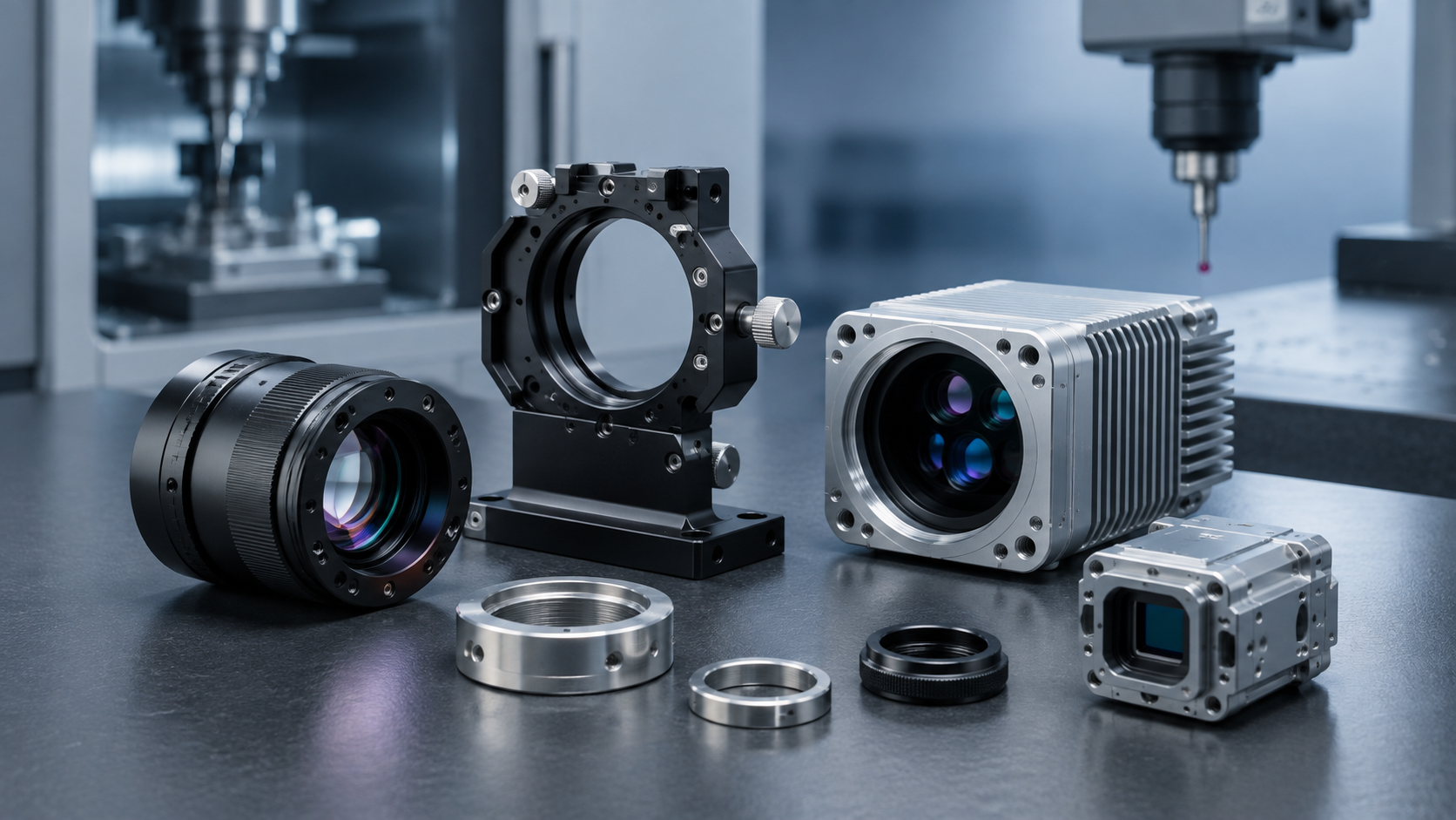
Ein CNC-gefertigtes optisches Bauteil kann alle Maßtoleranzen auf der Zeichnung erfüllen und dennoch während der Montage Probleme bereiten.
Warum? Weil die optische Leistung oft von der Beziehung zwischen den Merkmalen abhängt – nicht nur von der Genauigkeit jedes einzelnen Maßes.
Eine geringfügige Verschiebung zwischen Linsensitz und Befestigungsgewinde kann die optische Achse beeinträchtigen. Ein dünnwandiges Gehäuse kann sich nach dem Ausspannen verformen. Eine eloxierte Passung kann nach der Endbearbeitung zu eng werden.
Bei XY-GLOBAL gehen wir die optomechanische Bearbeitung mit Blick auf die Endmontage an. Der Fokus liegt auf Bezugssystemkontrolle, Konzentrizität, Rundlauf, Passungen und Montage-Wiederholgenauigkeit – nicht nur darauf, dass einzelne Maße die Inspektion bestehen.

CNC-gefertigte optomechanische Bauteile
Wir fertigen kundenspezifische Komponenten wie:
-
Linsentuben und Linsengehäuse
-
Linsen- und Spiegelhalterungen
-
Sicherungsringe und Präzisions-Distanzstücke
-
Kamera- und Sensorgehäuse
-
LiDAR-Gehäuse
-
Lasergehäuse
-
Optische Grundplatten
-
Filter- und Prismenhalterungen
-
Feingewinde-Einstellkomponenten
Diese Bauteile werden in der automobilen LiDAR-Technik, industriellen Bildverarbeitung, Laserausrüstung, wissenschaftlichen Instrumenten und medizinischen optischen Systemen eingesetzt.
Drei Herausforderungen, die bei der optischen Bearbeitung zählen
1. Konzentrizität und Rundlauf von Linsentuben
Problem:
Linsentuben enthalten oft mehrere Bohrungen, Linsensitze, Schultern und Feingewinde, die dieselbe mechanische Achse teilen müssen.
Optisches Risiko:
Das Umspannen zwischen den Arbeitsgängen kann geringfügige Verschiebungen der Bezugspunkte (Datums) verursachen. Einzelne Maße können zwar innerhalb der Toleranz liegen, während die Linsensitze und die Montageschnittstelle leicht zueinander versetzt sind.
Unser Ansatz:
Wo es die Teilegeometrie erlaubt, werden kritische koaxiale Merkmale von einem gemeinsamen Bezugspunkt aus bearbeitet und in so wenigen Aufspannungen wie möglich fertiggestellt.
Dies trägt dazu bei, akkumulierte Aufspannfehler zu reduzieren und die Kontrolle über Konzentrizität und Rundlauf zwischen Linsensitzen, Bohrungen, Passdurchmessern und Gewindeschnittstellen zu verbessern.

2. Verformung dünnwandiger Gehäuse
Problem:
LiDAR-Gehäuse, Kameragehäuse und andere optische Umhausungen kombinieren oft große Hohlräume mit dünnen Aluminiumwänden.
Materialspannung, Schnittkräfte und Spanndruck können dazu führen, dass sich das Teil nach der Bearbeitung verformt.
Optisches Risiko:
Verformungen um Sensor- oder Montageflächen können die Ausrichtung, Ebenheit oder Einbauposition verändern.
Unser Ansatz:
Je nach Konstruktion verwenden wir kontrollierte Vorrichtungen, eine ausgewogene Materialabtragung, gestuftes Schruppen und Schlichten sowie Zwischenkontrollen.
Bei verformungsempfindlichen Teilen wird die Bearbeitungsreihenfolge auf die Stabilität des Teils abgestimmt, anstatt das Material nur so schnell wie möglich abzutragen.
3. Feingewinde und Präzisionspassungen
Problem:
Linsentuben, Sicherungsringe und Fokussiermechanismen basieren oft auf Feingewinden und eng tolerierten Passflächen.
Optisches Risiko:
Übermäßiges Spiel kann zu Bewegungen führen, während eine zu enge Passung eine inkonsistente Montage oder Vorspannung verursachen kann.
Unser Ansatz:
Gewindepassung, Passflächen und kritische Maße werden während des DFM (Design for Manufacturing) vor der Produktion überprüft.
Die Oberflächenbehandlung wird in der gleichen Phase berücksichtigt, da Eloxieren oder Beschichten die Endmaße von Gewinden, Bohrungen und Passflächen verändern kann.
Toleranzspezifikationen & Inspektion
Bei geeigneten Geometrien und Merkmalen können kritische lineare Maße etwa ±0,005 mm erreichen.
Dies ist keine allgemeine Toleranz für jedes Maß an jedem Teil.
Die tatsächliche Leistungsfähigkeit hängt ab von:
-
Teilegeometrie und -größe
-
Material
-
Wandstärke
-
Dreh- oder Fräsprozess
-
Bezugssystem
-
Zugänglichkeit der Merkmale
-
Oberflächenbehandlung
-
Inspektionsmethode
Geometrische Anforderungen wie Konzentrizität, Rundlauf, Ebenheit, Rechtwinkligkeit und Positionstoleranz sollten individuell anhand der Zeichnung überprüft werden.
| Kritisches Merkmal | Fertigungsfokus |
|---|---|
| Linsensitz | Durchmesser und Bezugsbeziehung |
| Linsentubusbohrung | Konzentrizität und Rundlauf |
| Sensor-Montagefläche | Ebenheit und Position |
| Feingewinde | Passung und koaxiale Beziehung |
| Befestigungsbohrungen | Positionstoleranz |
| Dünnwandiges Gehäuse | Verformungskontrolle |
| Lineare Maße | Bis zu ±0,005 mm bei geeigneten Merkmalen |
| Oberflächengüte | Ra ≤ 0,8 μm auf geeigneten bearbeiteten Flächen |
Die Inspektionsmethoden werden je nach Merkmal und Toleranz ausgewählt, einschließlich Präzisionsmessgeräten, optischen Messsystemen und gegebenenfalls 3D-Koordinatenmessgeräten (KMG).

Gängige Materialien & Oberflächenbehandlungen
Typische Materialien sind:
-
6061-T6 und 7075-T6 Aluminium
-
Edelstahl
-
Messing
-
Kupfer
Aluminium ist besonders verbreitet für Linsentuben, optische Gehäuse und LiDAR-Komponenten, da es geringes Gewicht mit guter Zerspanbarkeit verbindet.
Typische Oberflächenveredelungen:
-
Schwarz eloxiert
-
Natur eloxiert
-
Harteloxiert
-
Chemische Konversionsschicht (Chromatierung)
-
Chemisch Nickel
-
Passiviert
Bei optischen Komponenten ist die Oberflächenbehandlung nicht rein kosmetisch.
Schwarze Oberflächen werden oft spezifiziert, um interne Reflexionen und Streulicht zu minimieren. Wichtiger noch: Die Schichtdicke muss dort berücksichtigt werden, wo Gewinde, Präzisionsbohrungen oder Passflächen die Endmontage beeinflussen.
DFM für optomechanische Bauteile
Eine nützliche DFM-Überprüfung identifiziert Fertigungsrisiken, bevor die ersten Teile hergestellt werden.
Wir überprüfen typischerweise:
-
Bezugssystem
-
Kombinationen enger Toleranzen
-
Koaxiale Merkmale
-
Dünnwandgeometrien
-
Feingewinde
-
Werkzeugzugänglichkeit
-
Aufmaß für Oberflächenbehandlung
-
Inspektionsmachbarkeit
Beispielsweise können mehrere Linsensitze und ein Montagegewinde um einen gemeinsamen Bezugspunkt herum neu konstruiert oder bearbeitet werden, um die Toleranzkette zu verkürzen.
Bei einem dünnwandigen LiDAR-Gehäuse können die Vorrichtungsunterstützung und die Abfolge der Materialabtragung vor der Produktion überprüft werden, um Verformungen zu reduzieren.
Bei eloxierten Passungen sollte die Beschichtungsspezifikation berücksichtigt werden, bevor die endgültigen Bearbeitungsmaße freigegeben werden.
Das Ziel ist nicht nur, ein Teil leichter zu fertigen. Es geht darum, die Funktion der optischen Endmontage zu sichern.

Warum mit XY-GLOBAL zusammenarbeiten?
Unser Ansatz basiert auf drei Prioritäten.
Optische Montageleistung, nicht nur Übereinstimmung mit der Zeichnung.
Wir berücksichtigen, wie Linsensitze, Sensorflächen, Bohrungen, Gewinde und Befestigungselemente nach der Montage interagieren.
Konsistente Bezugssystemkontrolle.
Kritische Merkmale werden, wo immer sinnvoll, auf gemeinsamen Bearbeitungsreferenzen gehalten, um Toleranzakkumulation und unnötige Rüstvariationen zu reduzieren.
Frühzeitiges DFM vor der Bearbeitung.
Toleranzbeziehungen, dünne Wände, Gewinde, Passungen und Oberflächenbehandlungen werden vor Produktionsbeginn überprüft.
XY-GLOBAL unterstützt CNC-Drehen, 3-Achsen- und 5-Achsen-Fräsen, Präzisionsinspektion, Prototypen und Serienfertigung.
Unsere Qualitätssysteme umfassen ISO 9001 und ISO 13485, wobei ISO 13485 besonders für optische Programme im Bereich Medizinprodukte relevant ist.
Erhalten Sie eine kostenlose DFM-Überprüfung
Entwickeln Sie einen Linsentubus, eine optische Halterung, ein LiDAR-Gehäuse, ein Kameragehäuse oder eine andere optomechanische Komponente?
Senden Sie uns Ihre:
-
2D-Zeichnung
-
3D-Modell
-
Materialspezifikation
-
Anforderung an die Oberflächengüte
-
Zielstückzahl
Unser Engineering-Team kann das Design auf Fertigungsmachbarkeit, Bezugsstrategie, Toleranzrisiken, Verformung dünner Wände, Passungen und Überlegungen zur Oberflächenbehandlung prüfen.
Die erste DFM-Überprüfung ist kostenlos und unverbindlich.
FAQ
Können Sie ±0,005 mm einhalten?
Bei geeigneten kritischen linearen Merkmalen ja. Geometrische Toleranzen und komplexe Merkmale werden gemäß Zeichnung separat geprüft.
Wie kontrollieren Sie die Konzentrizität von Linsentuben?
Wo sinnvoll, werden koaxiale Merkmale von einem gemeinsamen Bezugspunkt aus mit minimalem Umspannen zwischen kritischen Arbeitsgängen bearbeitet.
Benötigen Sie eine 2D-Zeichnung?
Eine STEP-Datei ist für die erste Prüfung nützlich, aber eine 2D-Zeichnung wird empfohlen, wenn Toleranzen, GD&T, Oberflächengüte oder kritische Bezugspunkte kontrolliert werden müssen.
Können Sie Prototypen fertigen?
Ja. Wir unterstützen Prototypen sowie die Serienfertigung.
Bieten Sie DFM-Unterstützung an?
Ja. Wir können Bezugspunkte, Toleranzen, dünne Wände, Gewinde, Passungen, Oberflächenbehandlungen und Inspektionsanforderungen vor der Produktion überprüfen.


Aktie:
Präzisionsdrehteile für kundenspezifische industrielle Anwendungen
Feinguss aus legiertem Stahl: Ein praktischer Leitfaden für komplexe, hochfeste Bauteile